Signal processing
Authors: Benjamin Chaix, Antoine Lorenzi
Contributors: Sam Irving
Air conduction hearing aids can be described in three components: the microphone, the amplifier/speech processor, and the speaker (or vibrator). This section describes how the acoustic signal is digitised and treated by principles of sampling and quantification.
The basic principle
The microphone captures environmental sounds and creates a variable electric current in the amplifier that depends upon the variations in the received sound pressure waves. This analog process (a variation in tension as a function of time) is comparable to the vibration and deformation of the healthy eardrum. Depending on the type of hearing aid, either directional or omnidirectional microphones are used.
The speech processor is the most complex part of the hearing aid. It is composed of two sub-stages: the microprocessor and the amplifier.
The analog signal is received from the microphone and digitised according to specific criteria: the sampling rate (A, B, C; the interval of time over which the signal is collected) and the quantification rate (which determines the number of bits) are responsible for the fidelity of the digital signal compared to the original analog signal (D, E, F).
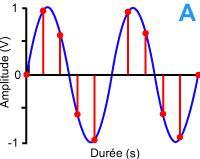
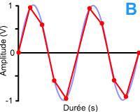
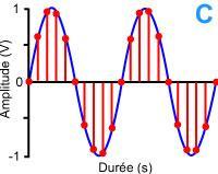
IMAGE: Amplitude (V) –> Amplitude (V)
Duree (s) –> Time (s)
Graph A shows a sinusoid sampled at a low sampling rate. When the points (B; samples) are joined, there is a significant amount of imprecision (compare the red line to the blue one). C shows the same sinusoid sampled at a high sampling rate. Joining these sampled points gives a much better representation of the original signal.
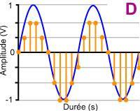
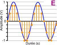
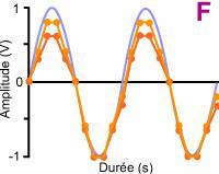
IMAGE: Amplitude (V) –> Amplitude (V)
Duree (s) –> Time (s)
Graph D shows inadequate amplitude coding of the selected samples, whereas E offers more precise coding for an equivalent sampling rate. Increasing the quantification increases the fidelity of the digital signal: it is similar to the original, analog, signal (F). There is a trade-off though – high fidelity processing is more labour-intensive and produces longer processing times.
A digital signal can undergo a number of different algorythmic modifications (such as filtering, compression…) with the aim of producing a signal that is adapted to the hearing profile of each hearing impaired patient:
- Automatic gain control (Input; AGC I): this system allows the gain provided by the amplifier to be controlled depending upon the input level – higher volumes require less amplification
- Automatic gain control (output; AGC O): like the AGC I, this system controls the gain, but this time it occurs after amplification. This results in lower gain for higher output levels. Currently, AGC I is preferred for gain regulation, and AGC O is used predominantly to minimise the output level of the device. The latter is similar to peak clipping.
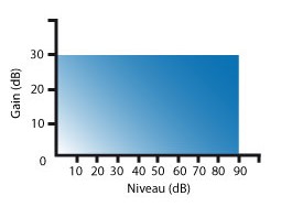
This graph shows the evolution of gain as a function of the level of sound. It is constant (or linear) to 90 dB, where the signal is clipped (it has infinite compression). Clipping strongly degrades the quality of the output signal.
FIGURE:
Gain (dB) —> Gain (dB)
Niveau (dB) –> Level (dB)
Currently, new hearing aids change the gain as a function of the input and/or output levels. As a result, non-linear amplification is obtained, which has the aim of approximating a patient’s loudness sensation. This non-linearity translates the existence of a compression rate; the higher it is, the faster the gain decreases.
Generally, the output limiter on hearing aids is set by a AGCO with high compression levels.
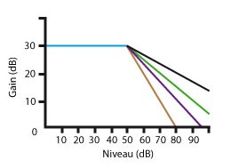
This graph shows the evolution of gain as a function of the entry level of a sound. It is constant (or linear) to 50 dB, after which a decrease in gain is observed. The speed of this decrease is defined by the compression rate: Black (1.5:1); Green (2:1), Purple (3:1).
The brown curve represents the output limit of an AGCO with a compression rate of 100 and the onset threshold of 80 dB.
When the desired modifications have been carried out, the signal is once again converted to an analog signal to be amplified. This amplification can occur at the input or the output, depending upon the processing strategy used.
The speaker, simply a wire coiled around an electromagnet, reproduces the altered signal. The coil receives the variations of the output current and sends them to the membrane of the electromagnet to cause motion of air molecules.
In the case of middle ear implants, the speaker is generally a small electromagnetic piston that has been surgically affixed to the descending branch of the incus. It receives the variations in current and transmits them mechanically to the stapes.
A few things to consider about adjustments and adapation
It is obvious that in the case of hearing loss, amplification of sound intensity becomes a necessity. However, it does not resolve all issues.
For example, the majority of patients with presbycusis suffer from recruitment: their dynamic range is decreased, particularly at higher frequencies. Amplification (non-linear, if possible) should be applied, integrating signal compression to avoid passing the threshold of tolerance.
Compression can be applied in an independent manner across different frequency bands in the amplifier. Compression and frequency transposition systems can also be used to limit amplification in the high frequency range (input sounds of higher frequency at a defined value (Fc) are reconstructed in a frequency range that is lower than Fc).
Adaptation in hearing aids needs to be precise. The hearing professional should provide support and encouragement as the process of fitting can be long and complex. First contact is very important and a trusting environment is essential. It is good to gauge the personality of the patient to obtain better results, and to take into account other factors such as age, manual dexterity, visual acuity and motivation, in order to maximise their adaptation ability.